The Conversation (0)
Sign Up
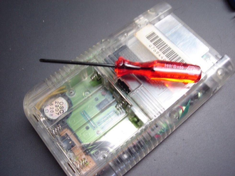
the triwing screwdriver is an integral part of this mod. Nintendo use a non-standard screw on the 6 found on the outside of the case.
step one is to remove the screws. There are six triwings on the back of the DMG. Four are visible, and two are hidden under the battery compartment. make sure you don't loose these screws.
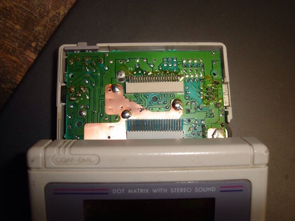
Now you need to disconnect the display cable. BE VERY CAREFUL! The ribbon cable that connects the dot matrix display to the gamboy's motherboard is very thin.
The cable has minimal metal on the leads at the end. So if you scrape any of it off by pulling it out too hard or at a strange angle, you can expect some dead pixels. Just pull it straight down.
For anybody this happens too, leave a comment on here, and I'll make a guide on fixing the screens dead pixels, if needed. :)
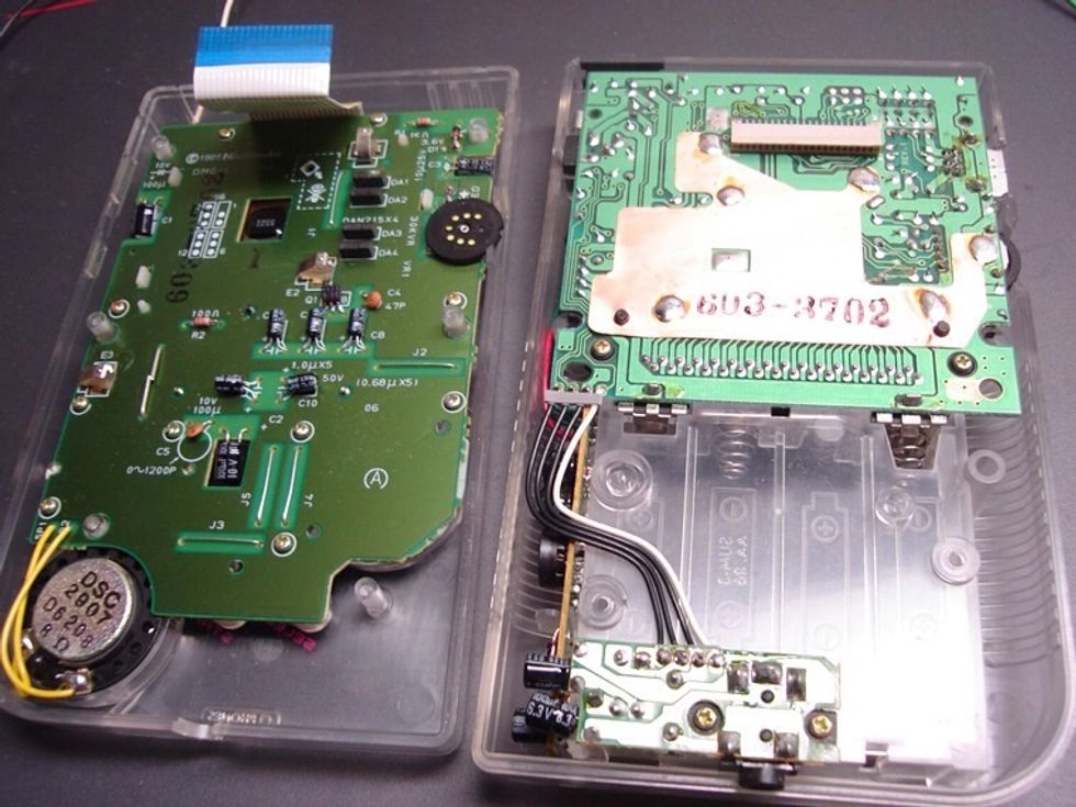
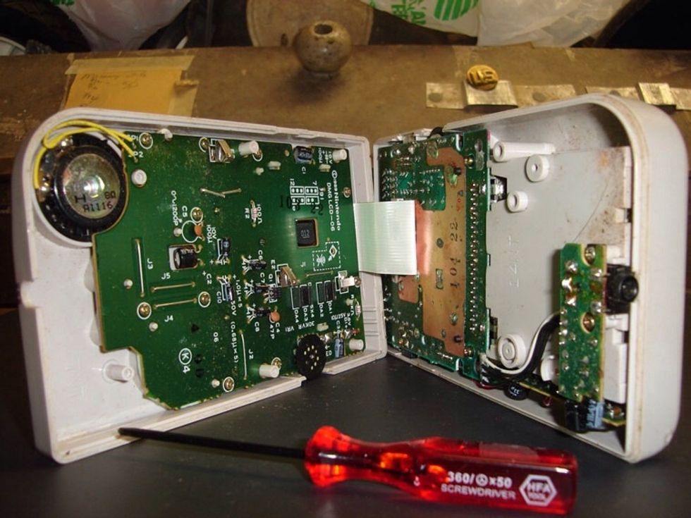
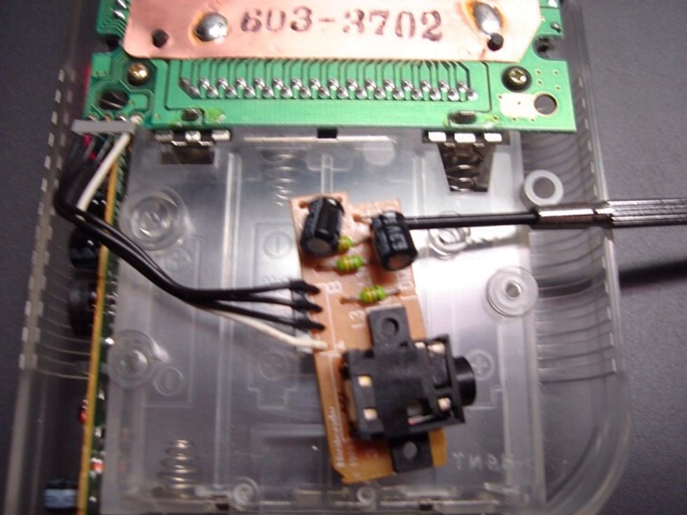
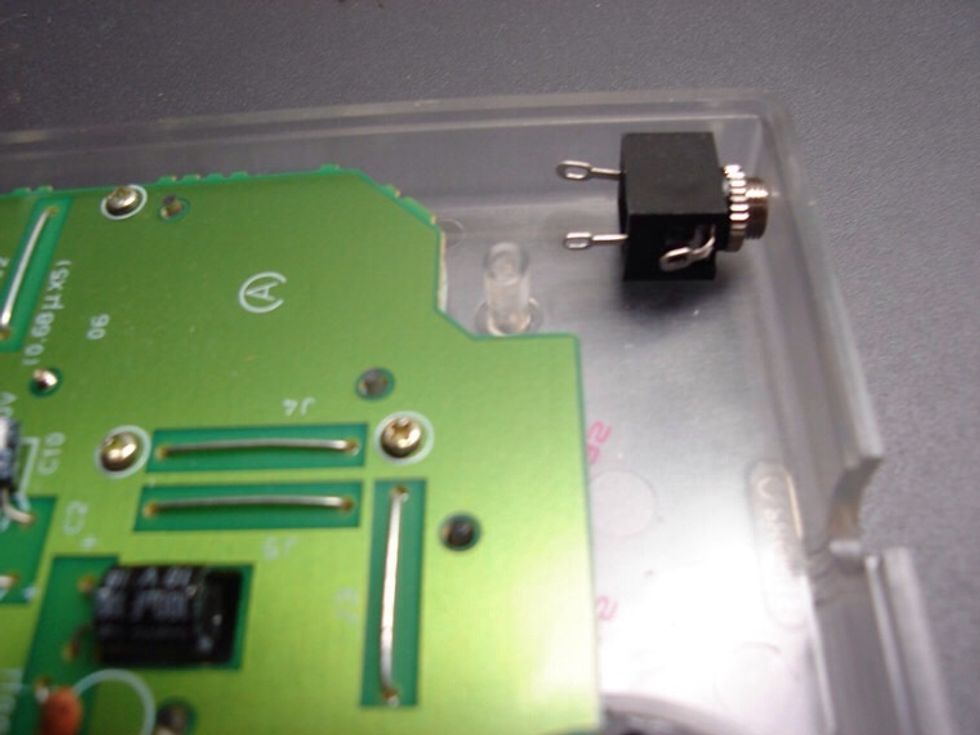
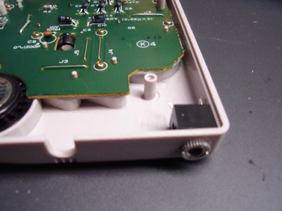
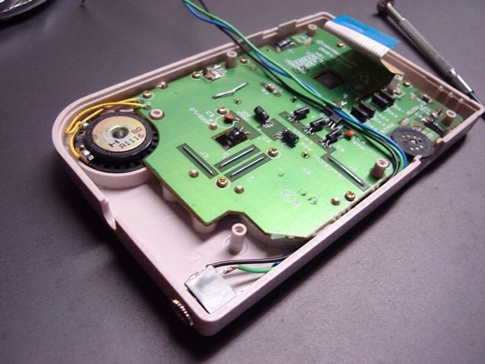
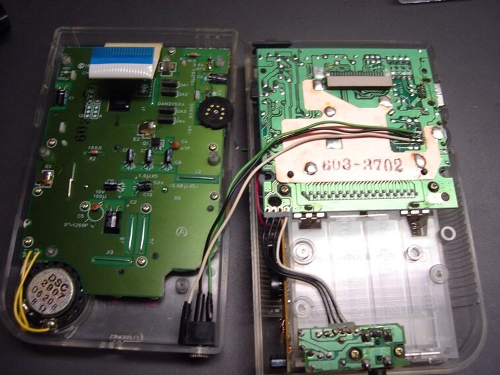
Now take a moment to check out the inside of the gameboy. In the image above you can see the 3 points on the board we're going to be soldering to. Check step 7 for the wiring diagram.

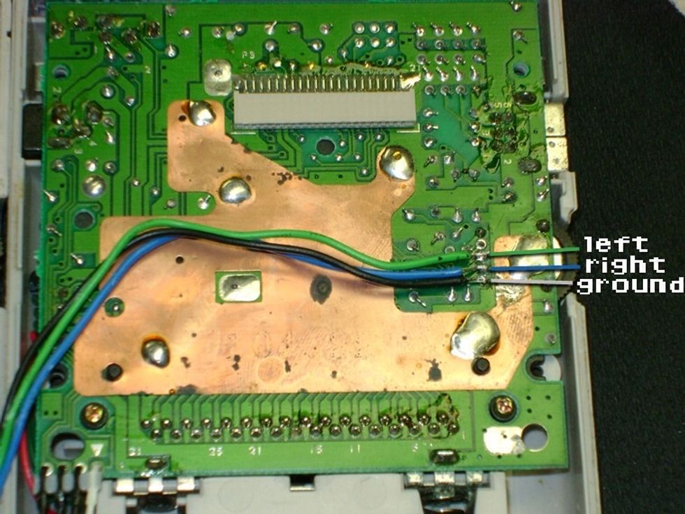
The wiring diagram. Displaying the location of the left, right, and ground wires.
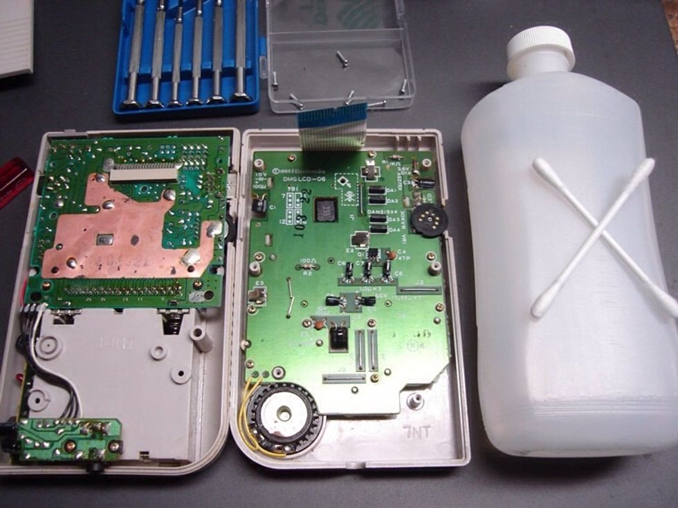
The next step is optional. But its normally necessary. Clean everything. All you need is the highest percent alcohol you can get (i use 98%) and some cue-tips. Get into those little recessed areas.
Make sure you do the battery terminals too, especially if they have any corrosion on them. That process may require paper towels, and some extra elbow grease.
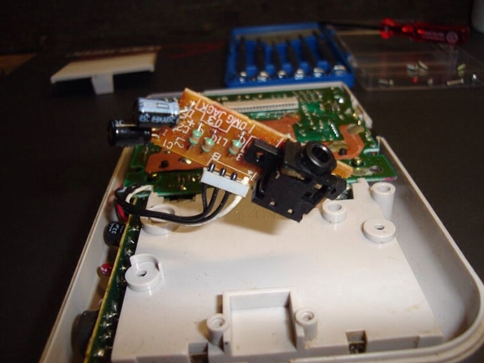
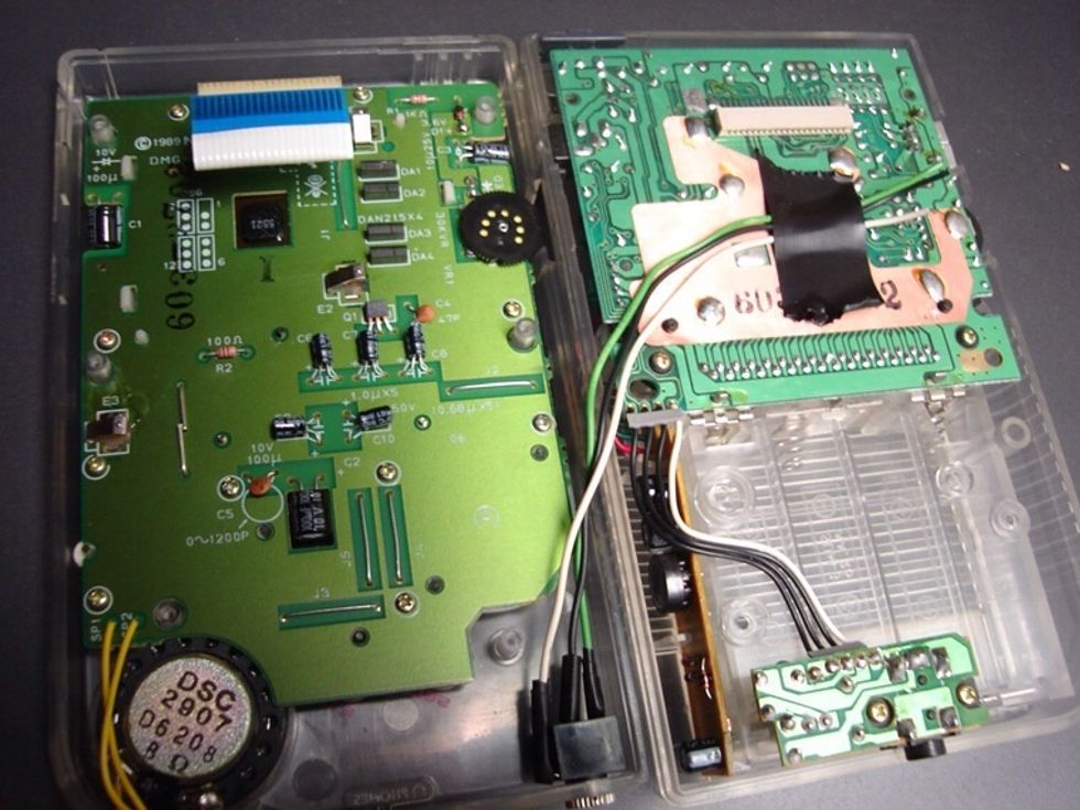
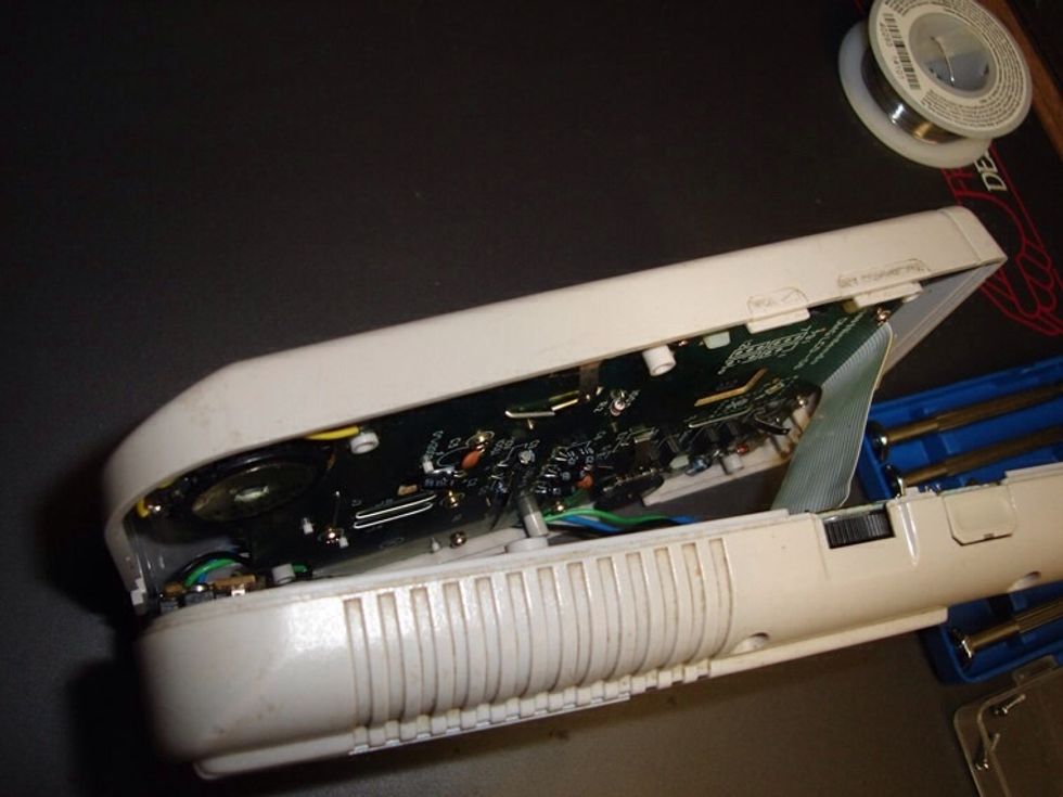
To fix the jack into the case you'll need to make a little more room. Use a mini-philips head screw-driver to remove the audio board with the headphone jack on it.
Now take your screw driver and place it between the board and the capacitors. Very carefully bend the leads so the capacitors lay flat against the board as opposed to pointing outwards from it.
Now screw the board back into place. Make sure it still lays flush inside the case. Don't force it to fit, just carefully rebend the capacitor leads until it fits correctly.
At this point, if you accidently break one of the leads from bending them too much, you'll have to resolder them, so there's still a connection.
Now that we have the space in the case, decide where you're going to mount the 1/8" jack. You don't have a lot of room to work with, so get the jack as far on the edge of the case as you can.
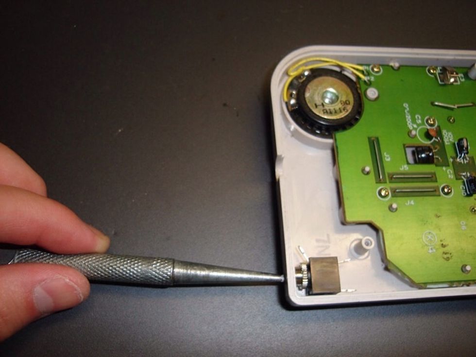
Now use an awl or marker pen to mark where you are going to drill your hole. Press it into the center of the jack, about where the cord will be inserted, until you have a visible mark on the plastic.
You don't have to actually break the plastic, but make a mark on it. This will help you a lot when drilling. This gives the drill or dremel a place to start at so all you need to do is press.
When drilling make sure you wear goggles, and make sure the Gameboy is safe and secure. We don't want it to break. You have music to produce!
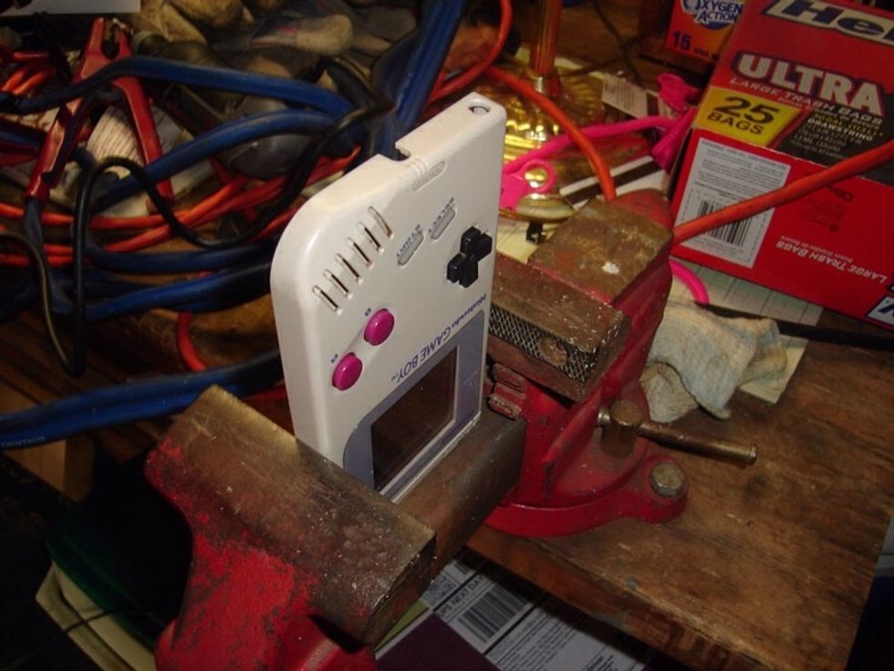
To keep the gameboy steady when drilling, i put it into a vice. It was a hard decision whether long or short way was the best position. Do what seems best for your situation.
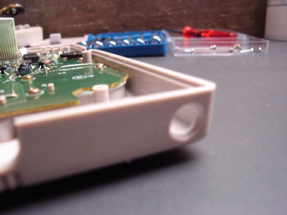
After your first pass you should have a small hole in the case of the DMG. The edges will be rough and uneven. But that's ok for now.
Now stop the dremel. And unscrew the end of the 1/8" jack. Try and fit it into the hole you just made.
If it's a little small, turn the dremel on a low setting and go over the edges again, and keep checking until the jack fits tightly in the hole.
By going over the edges repeatedly you will also get a nice smooth flush finish and a tight fit.
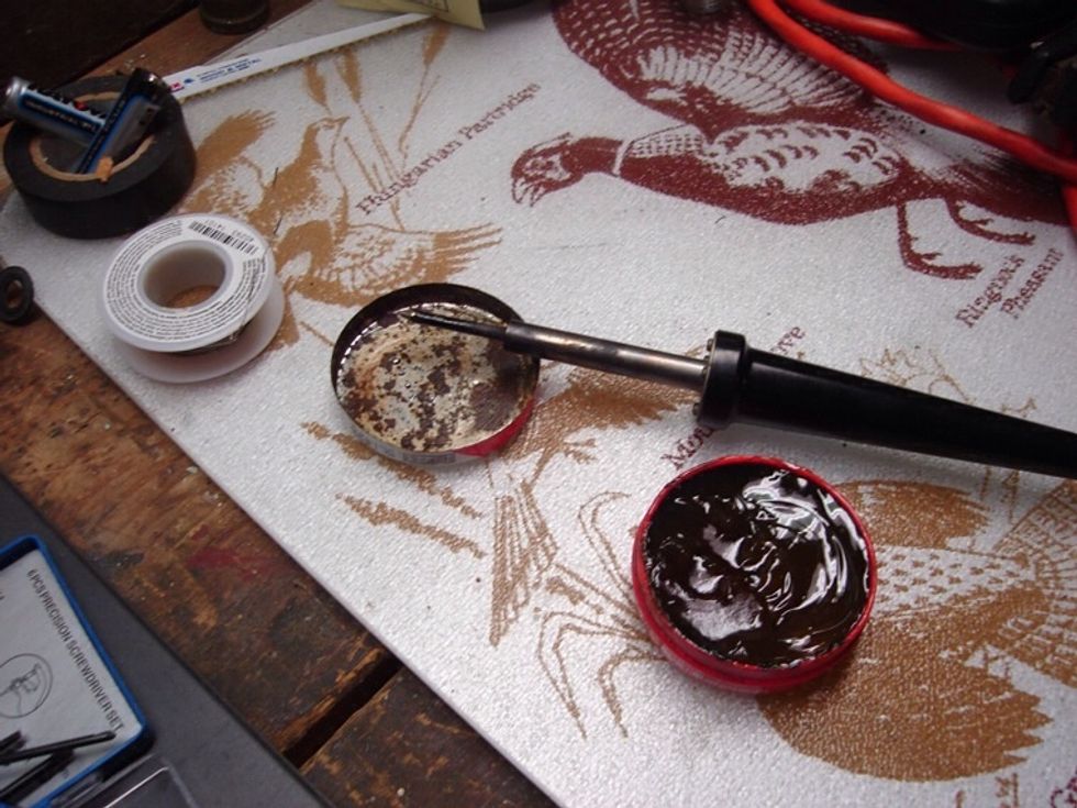
Now is a good time to plug in your soldering iron. It will start getting hot while your doing the prep work for the next stage.
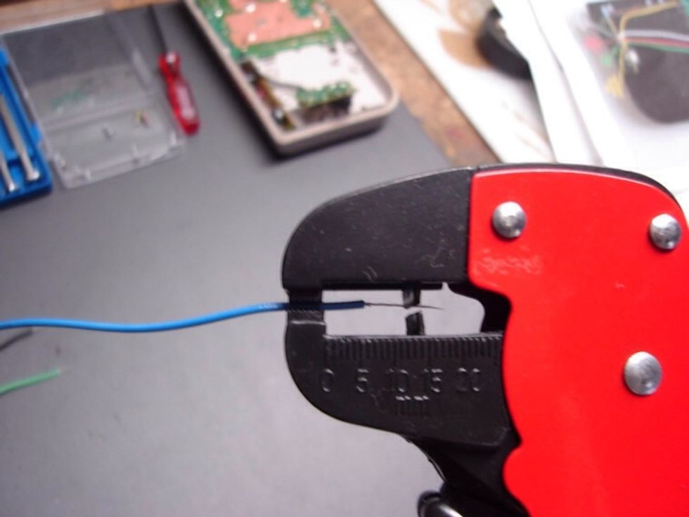
Get your three wires ready, and strip both ends of each wire. I left one end of the wire a little longer for the jack, and the other end very short for attaching to the board.
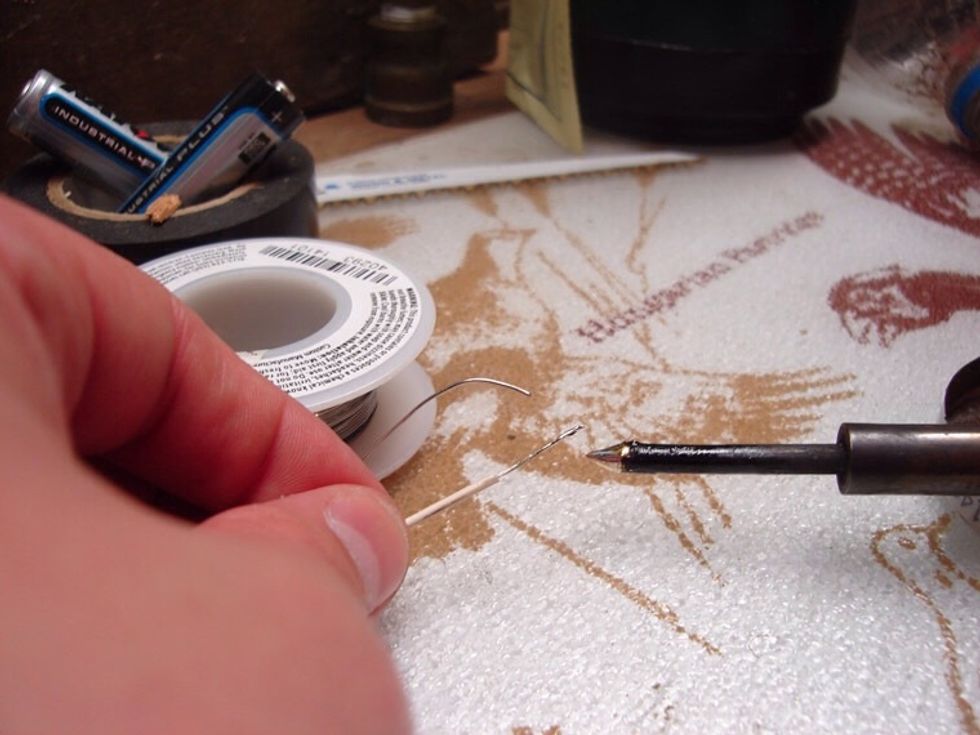
After that i suggest you tin the wires. Dip your iron in a little flux to clean it off, then get a tiny drop of solder on the ends of each wire. This will make attaching them a lot easier.
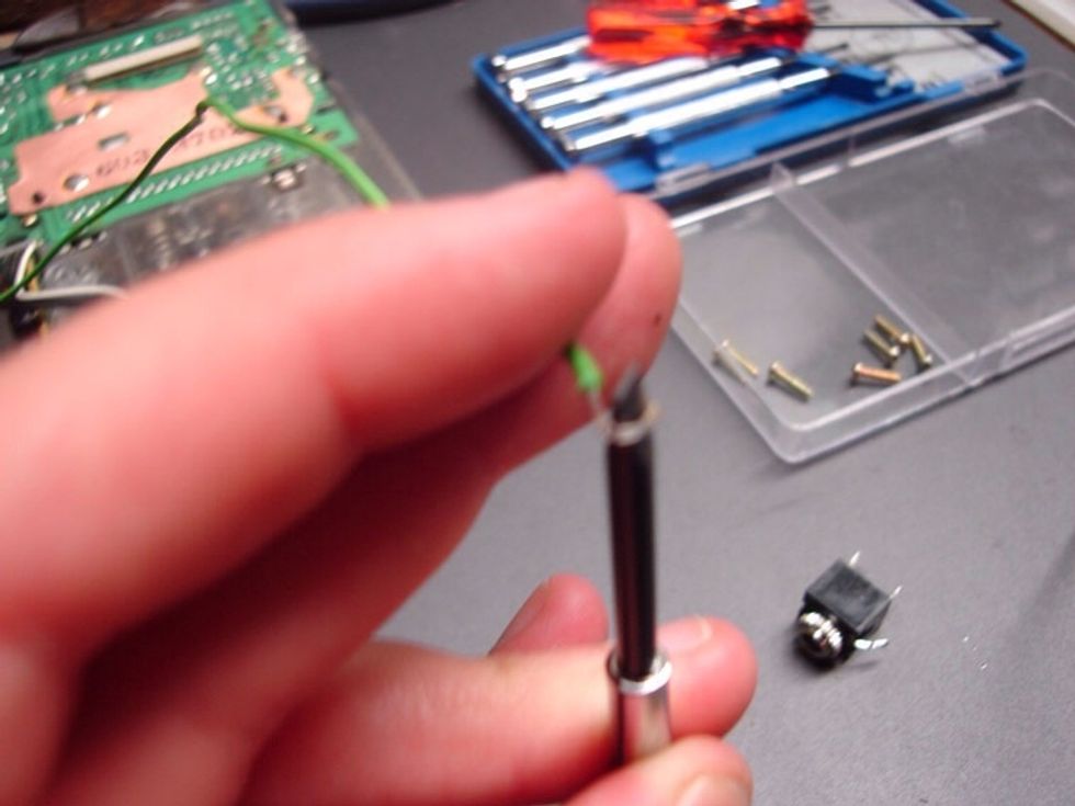
Now take the longer ends of the wire and wrap them around the end of a flat head mini screwdriver. this will make a little "hook" at the end of the wire (that's why we made them a bit longer).
At this point depending on which jack you're using, the longest central part is the 'ground', the bronze is the 'right', and left is the 'silver' one. These need to match the wires to the gameboy.
Then take the wires and hook one on the end of each of the prongs of the 1/8" jack connector.
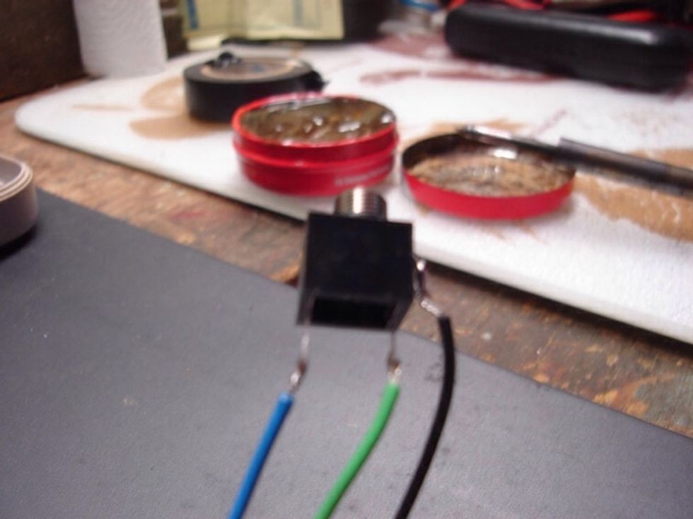
Now that the wires are hooked on the jack, take your screw-driver and flatten the hooks so they don't move as much. Now just take a tiny dab of solder and attach the wires to the jack.
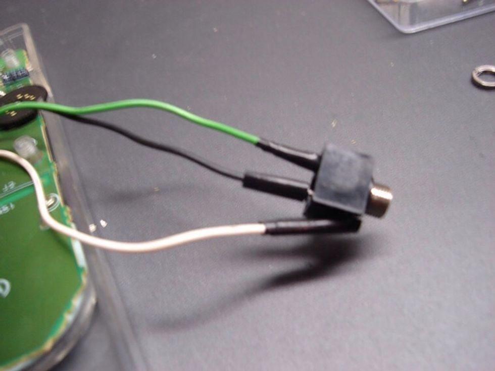
To avoid any cross talk that might possibly occur between the wires (however unlikely) wrap them up. Either use some heat shrink tubing or some electrical tape around the edges.
Now mount the jack in the gameboy case. Put the end of jack into the hole you drilled from inside the case.
Then screw the end piece back on from the outside. To optimize space, put the ground wire on the open side so the jack lays flush against the case sidewall.
Now take a pair of pliers and tighten the end of the jack as much as possible. Just be careful not to scratch the exterior of the gameboy's case when doing so.
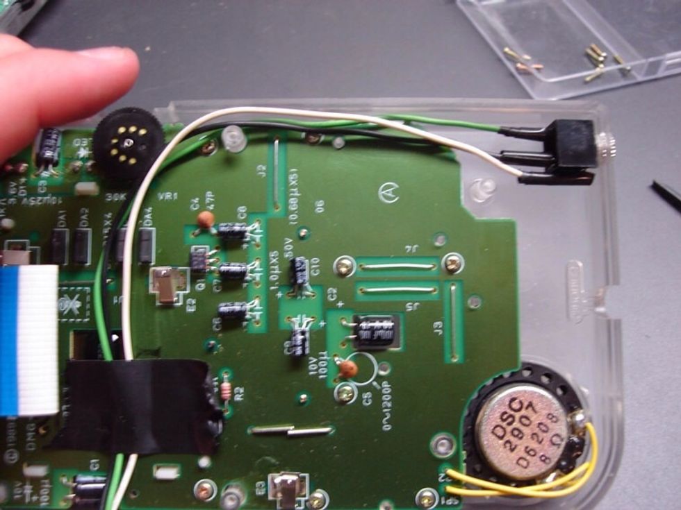
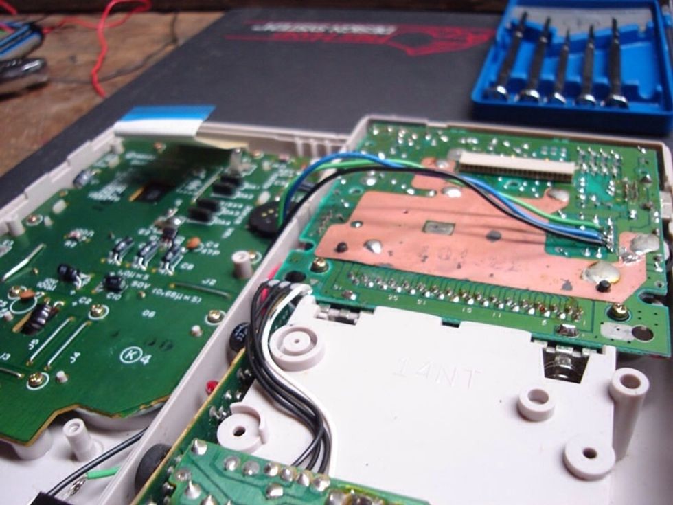
The next step is very important. Getting the wires ready to solder onto the board. Make sure that the wires are not touching the contrast dial.
After a few tries of routing the wires and test closing the case, i actually made the wires a lot shorter. This made the process of closing the case at the end a lot easier.
Once you get the wires in the right place tape them down. Just remember the old saying, measure twice solder once. I like to double that, just in case.
There's 5 solder points that connect the potentiometer to the gameboys board.
The top 2 we are going to ignore. They are volume into the pot. The next 2 are the left and right audio out of the pot and finally the ground.
When it comes to solder, less is more. The amount of solder to use varies from gameboy unit to unit.
When doing this take your time. Make sure you are connecting the correct prongs of the jack to the right pins on the board.
The wiring pinout diagram should be on the packaging of the jack, and varies from model to model.
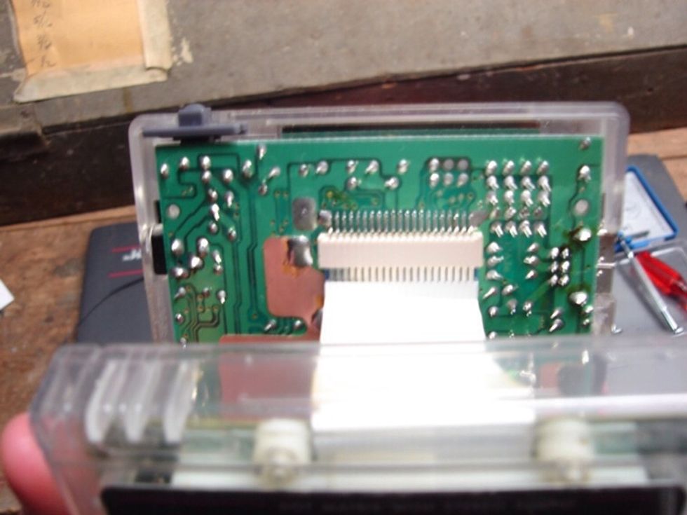
Now carefully reconnect the display cable. Put your fingers under the edge on the ribbon cable and push it up into place.
Don't try and rock the cable back and forth to get it into place. This could rub off some of the metal on the leads. The photo is the cable fully inserted. Notice how much metal is still showing.
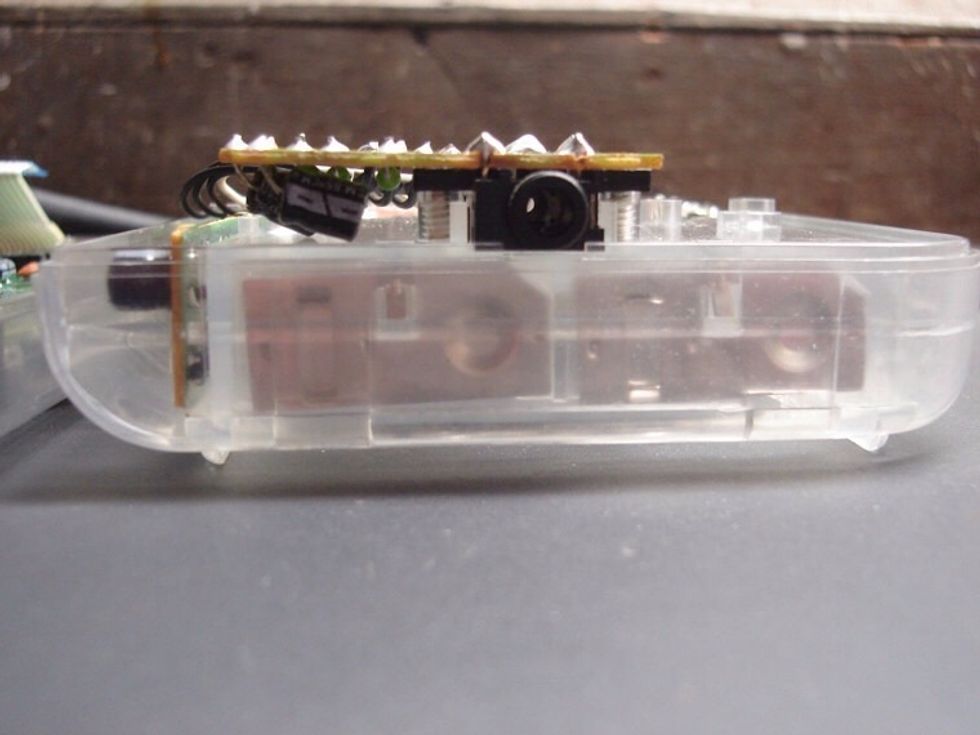
The final step is closing the case. This can be tricky. So take your time.
Make sure none of the prosound jack's wires are sticking out or stuck between the edges of the case when closing it. Also keep the wires clear of the contrast dial.
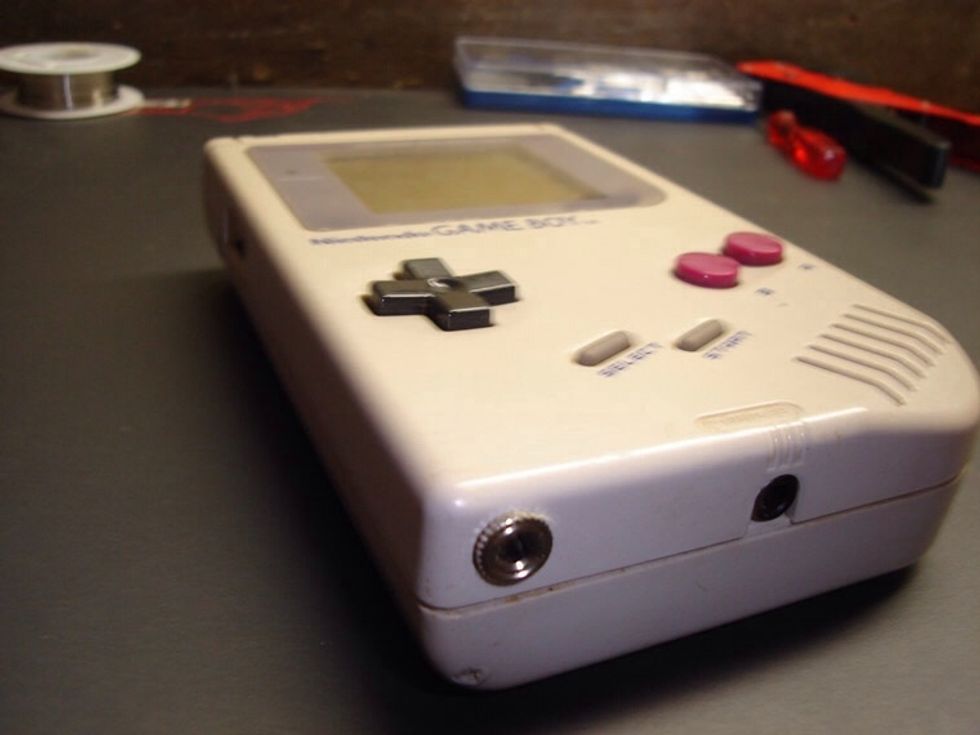
Now your gameboy is prosound modified! the added jack will reduce background noise when recording and actually increase volume and give you added bass because it's a line level output.
CONGRATULATIONS! Now pop in your favourite 8-bit music application, and make some chip-tunes!