The Conversation (0)
Sign Up
This device can be mostly made with components you likely have laying around. With this version I purchased a few more of the parts but the main things need are a bridge rectifier and a regulator.
A Bridge Rectifier is required for this project. I will convert the AC coming out of the hub to DC for use in the light and input to the regulator. I used a W04M 1 Amp Rectifier.
For the regulator I used the Pololu S18V20F5 ($15), but either 5V S7Vxxx ($6/$5) will work. In a pinch the ever popular LM7805 5V regulator will work. Although it is less efficient.
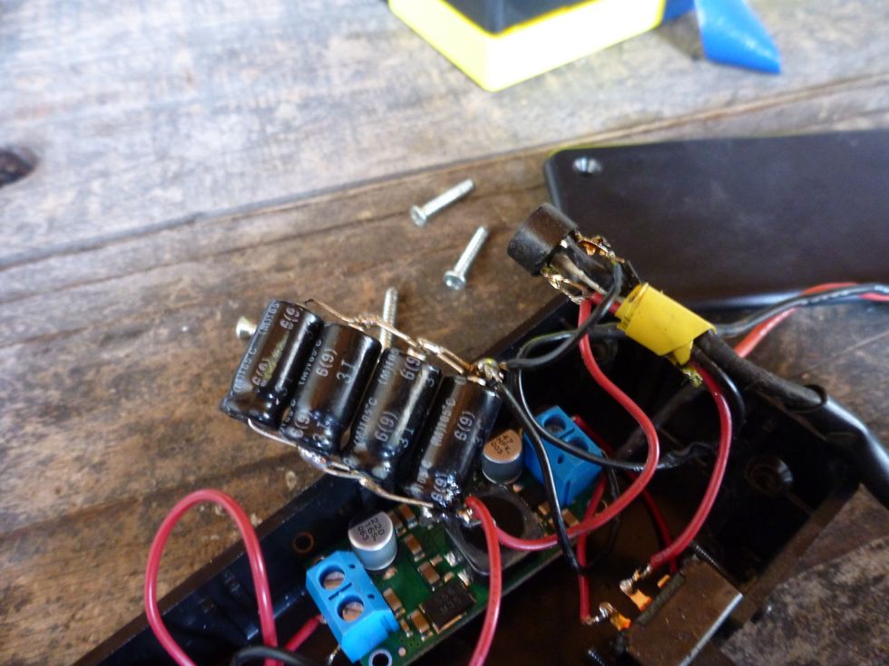
The bridge rectifier is connected to the Dyno Hub output and has the capacitors connected between the +/- to help smooth out flicker the light and help the regulator keep running.
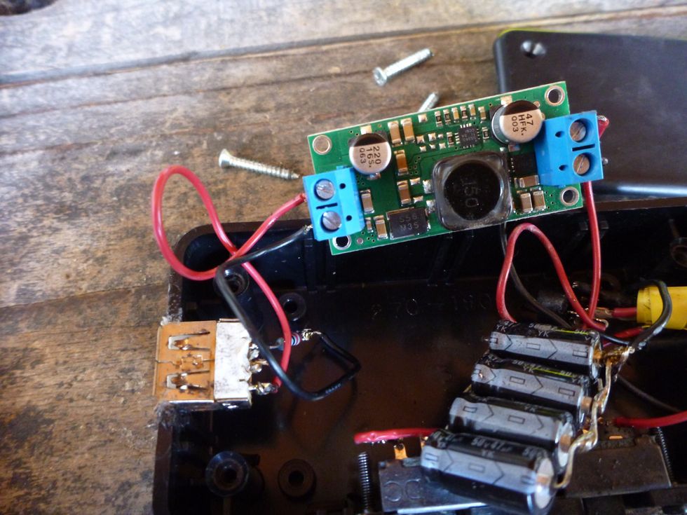
Output of the regulator is connected to the +5V / GND of the USB port.
Number of capacitors is up to you. You'll need at least a couple decent sized ones to prevent the light flickering at low speeds. More means the light will take longer to come on, but stay on longer.
USB Connected in the project case. The upper switch controls the USB power. Lower switch is for the light.
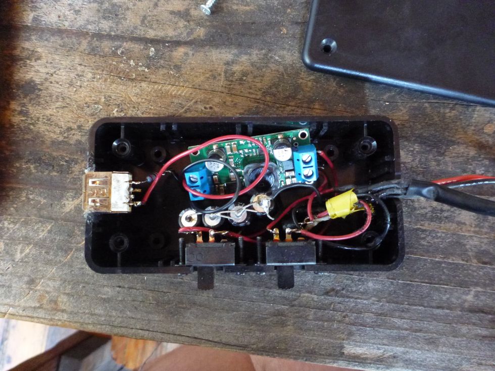
The switches are connected inline on the + lines for the USB (pre-regulator) and the light. The entire case was cut with a box knife and the USB port was glued in.
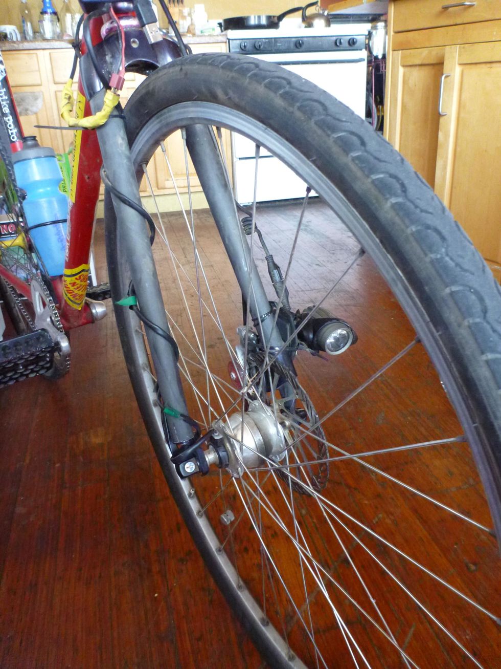
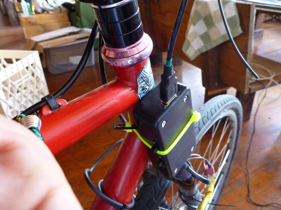
I used a repurposed headlamp but any LED lamp should work. To wire it up I wrapped the Dyno cable up one leg and the light cable down the other. Optional light connector can be seen in the upper left.
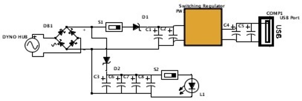
Schematics! This is the latest revision with separate cap banks for each side of the circuit and zener diodes to isolate them.