The Conversation (0)
Sign Up
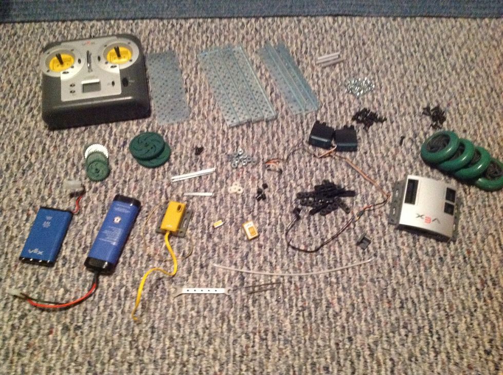
Supplies You'll Need...
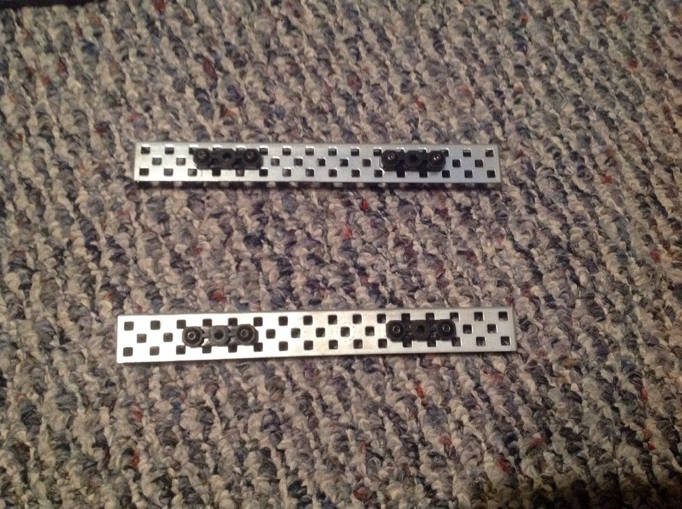
1. Take two Chassis Rails and four Offset Pieces; place the Offset Pieces on the Rails as shown on the picture. Then, fasten the Offset Pieces with 8 Keps Nuts and 8, 8-32 1/2" Screws
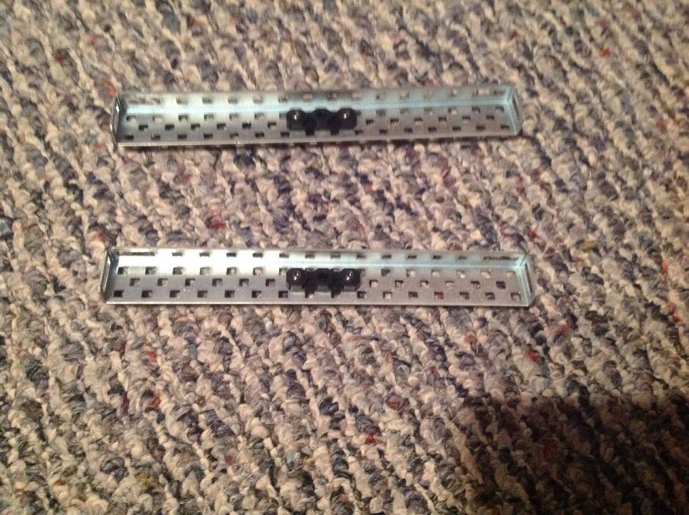
2. Take the other two Chassis Rails and place two Offset Pieces on the inner side of the Rails as shown. Then, fasten them with 4 Keps Nuts and 4, 8-32 1/2" Screws.
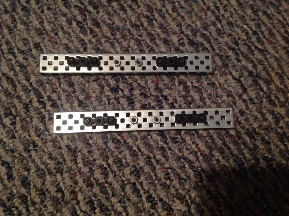
3. Next, attach 4 Offset Pieces to the outside of both Rails in the same place and method as you did in Step One.
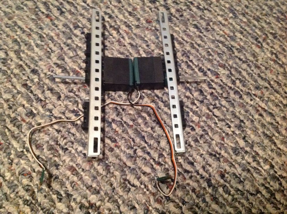
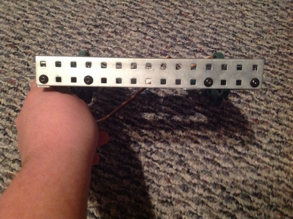
![4. Take both Motors (ensure the clutch [thick green ring] is inserted) and insert a 2" Square Rod into both clutches. Then, put the Square Rods through the Chassis Rails made in Step One](https://guides.brit.co/media-library/4-take-both-motors-ensure-the-clutch-thick-green-ring-is-inserted-and-insert-a-2-square-rod-into-both-clutches-then-put.jpg?id=23854437&width=980)
4. Take both Motors (ensure the clutch [thick green ring] is inserted) and insert a 2" Square Rod into both clutches. Then, put the Square Rods through the Chassis Rails made in Step One
5. Slide another Offset Piece over both Square Bars on the outside. Refer to the picture for where to place it. Then, secure to the body with four, 6-32 1/2" Screws (2 on each side).
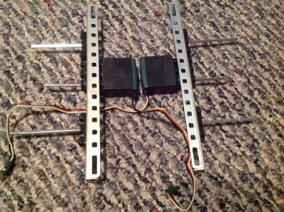
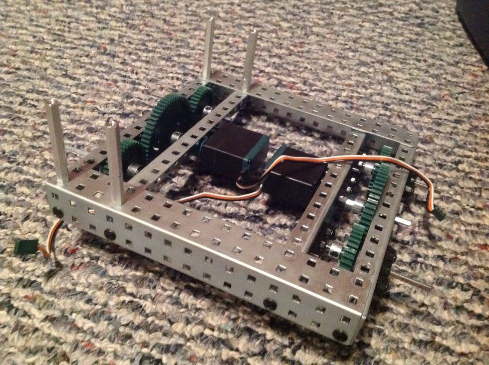
6. Take four 3" Square Bars and slide through each unoccupied Offset Piece on both Chassis Rails. Slide through leaving only a little bit on the inside.
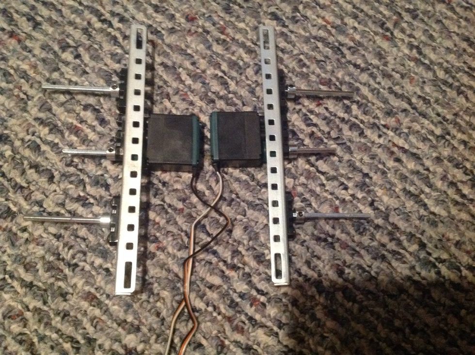
7.Next, take six Metal Collars and slide over the outside of the Square Rods. Fasten once Collar is against body; refer to the picture for help.
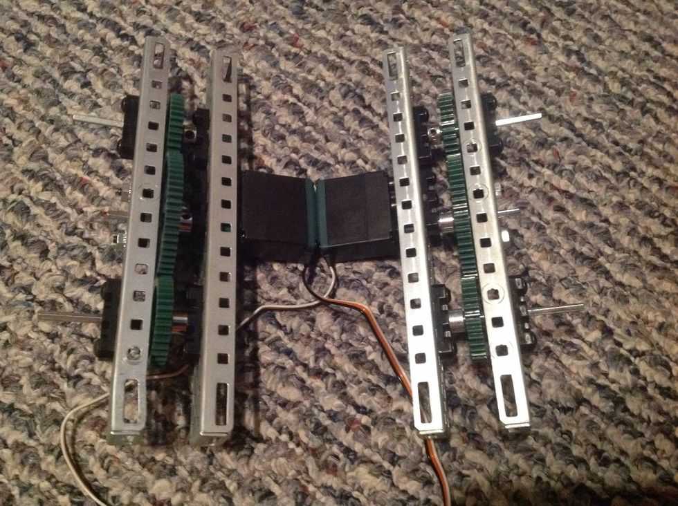
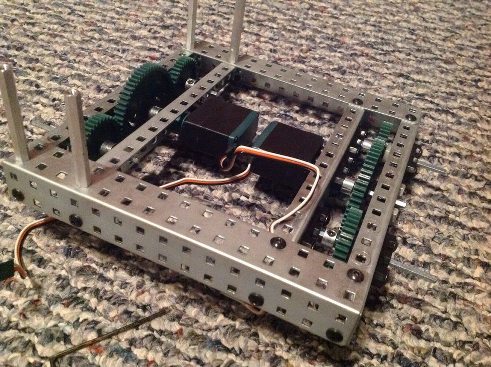
8. Slide 60-Tooth Gears over center Square Rods and 36-Tooth Gears over left and right Square Rods. Add a Long and Short Spacer over left and right Square Rods. Slide Step two's Rails over the body.
9. Take both Chassis Bumpers and add to both ends of the body as shown. Fasten using 4 Keps Nuts and 4 8-32 1/4" Screws on each side (8 of both in total).
10. Take four 2" Threaded Beams and secure to the chassis where shown with 4 8-32 1/4" Screws.
11. Use 4 8-32 1/4" Screws and 4 Keps Nuts to further secure the chassis to Chassis Bumpers where shown. Also, insert the Wheel Hubs into the Rubber Wheel Covers.
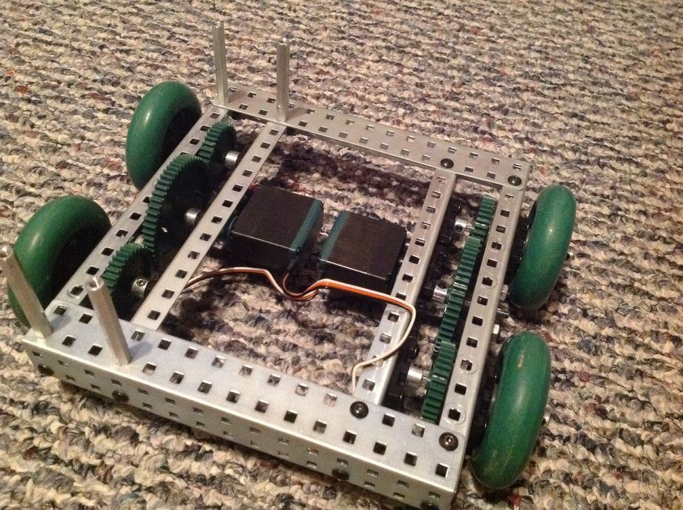
12. Slide the Finished Wheels over all four left and right Square Rods. Take 4 Metal Collars and slide on all four left and right Square Rods. Secure once against wheels.
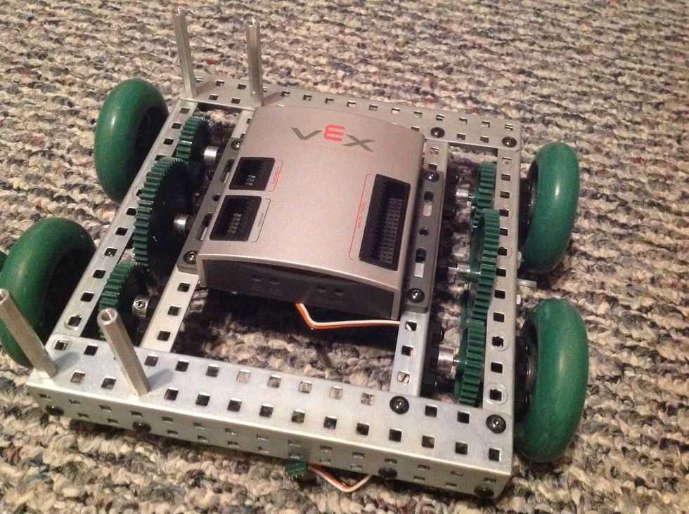
13. Take the PIC Microcontroller and secure to chassis with 4 8-32 1/2" Screws and 4 Keps Nuts. Exact placement is not very important but you may use the picture as reference.
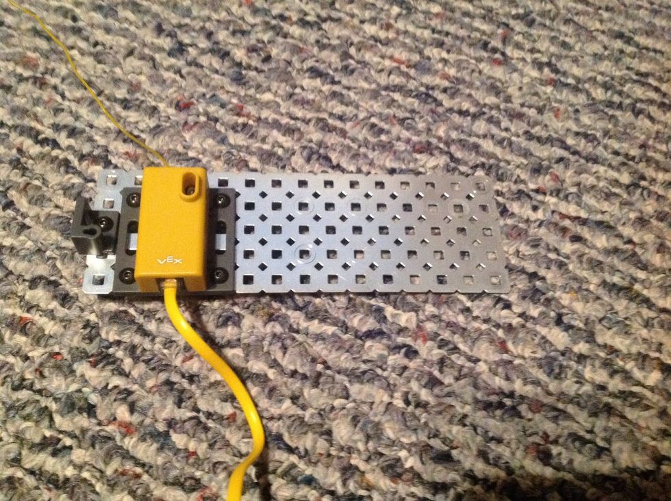
14. Connect the Yellow Receiver to the Flat Chassis Panel. Connect with 4 8-32 1/4" Screws and 4 Keps Nuts. Then, connect the Antenna Base to Flat Chassis Panel with one 8-32 3/4" Screw.
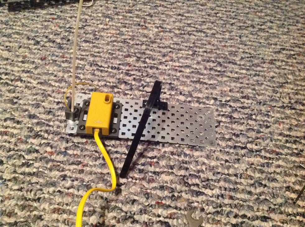
15. Next, carefully slide the antenna through the Antenna Tube and insert into the Antenna Base. Connect the Battery Holder to the Flat Chassis Panel with 2 8-32 1/2" Screws and 2 Keps Nuts.
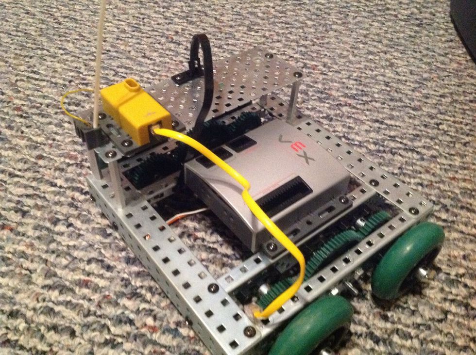
16. Connect the Flat Chassis Panel to the main body with 4 8-32 1/4" Screws inserted through the Flat Chassis Panel into the previously fastened 2" Threaded Beams.
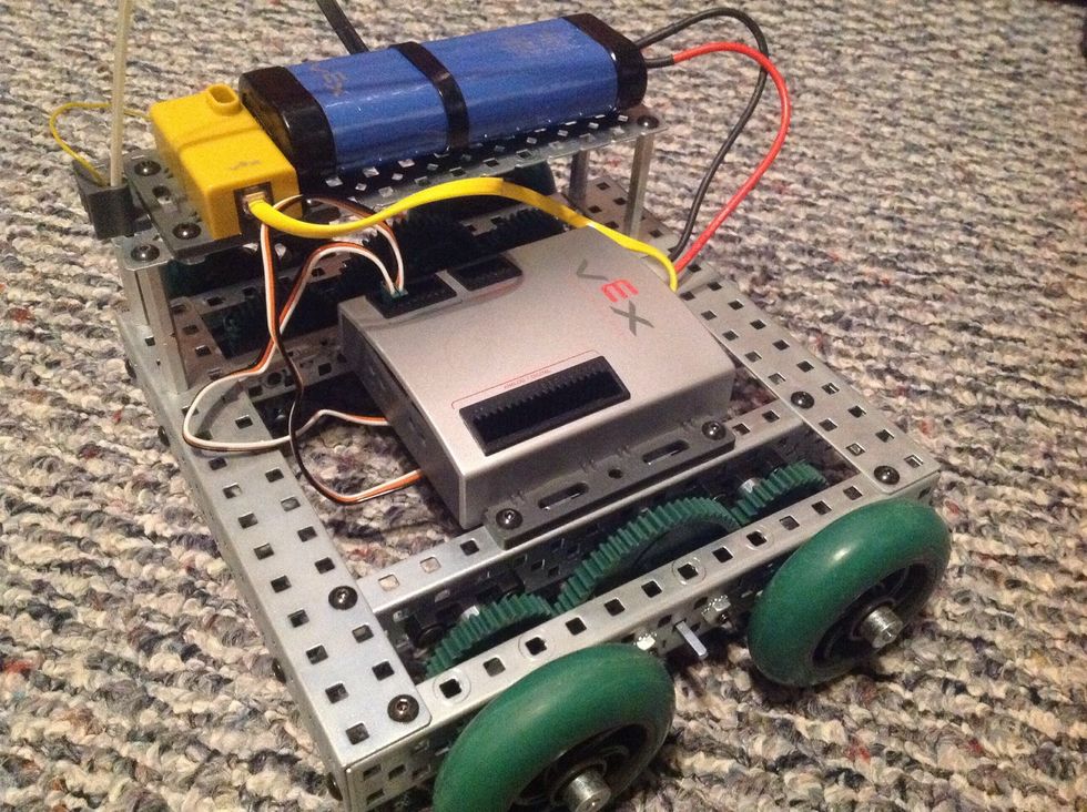
17. Connect the plugs on the motors to Motor Ports 2 and 3 on the PIC Microcontroller. Plug in the Robot Battery to the Microcontroller as well as the receiver to its appropriate location.
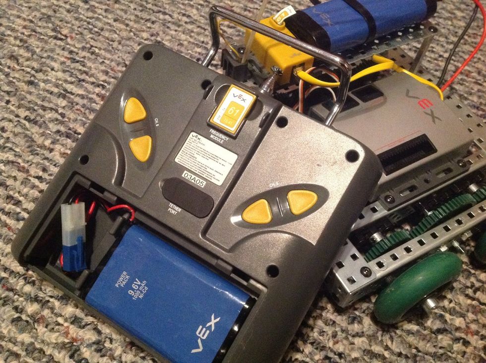
18. Plug in both crystals to where they belong. Hit the power on both the Robot and Controller and have fun! Go To: http://www.robotc.net/support/vex/media/build/docs/squarebot.pdf For More Help...